
A small measurement error in diesel fuel transfer can become a costly problem when thousands of liters are involved. It may show up as a difference between delivery records and actual inventory, or create disputes over the quantity of fuel supplied. For fuel distributors and industrial operators, the accuracy of the flow meter is therefore more than a technical specification.
Behind a reliable meter are several manufacturing steps that need to work together. Sensor selection, machining accuracy, assembly tolerances and calibration all affect the final measurement. A modern Flow Meter Factory needs to control these details rather than relying on the sensor technology alone.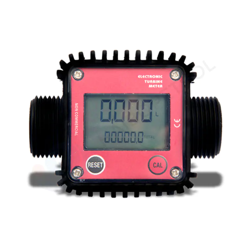
Different Flow Meter Technologies Suit Different Applications
There is no single measurement principle that works equally well for every diesel transfer system. Fluid viscosity, required flow rate, operating pressure and installation conditions all influence the choice.
Three technologies are commonly considered:
Buyers should provide the expected minimum and maximum flow rates, fuel characteristics and required measurement accuracy before selecting a model. Choosing a meter based only on pipe diameter or purchase price can lead to problems later.
Manufacturing Accuracy Matters, Especially in Mechanical Meters
In an oval gear meter, the dimensions of the gears and measuring chamber have a direct influence on how fluid passes through the instrument. Variations in gear geometry, bearing clearance or internal surface finish can affect measurement consistency.
The machining and assembly processes therefore need close control. Important operations include:
Wetted materials also need to suit diesel fuel and the intended operating conditions. Metals, seals and other internal components should be checked for compatibility with the fuel composition, temperature and pressure involved.
Electronic Processing Makes Flow Data Easier to Use
Electronic flow meters convert sensor signals into readings that operators can monitor, record or send to other equipment. Depending on the model, available functions may include instantaneous flow rate, accumulated volume, pulse output, digital communication and alarm functions.
These features are useful in automated fuel transfer systems. Operators can monitor quantities during delivery and connect measurement equipment to a control system or data logger.
But digital processing cannot repair a poor mechanical setup. Electrical interference, unstable power, incorrect installation or a sensor operating outside its specified range may still produce unreliable readings.
Manufacturers need to validate the complete signal chain, from the sensor to the displayed value and external output.
Account for Temperature and Viscosity Changes
Diesel properties change with temperature. As temperature changes, fuel density and viscosity also change, and different meter designs respond to these changes in different ways.
In positive displacement meters, viscosity can affect internal leakage and friction. In turbine meters, it can influence rotor behavior and measurement performance.
Some instruments use temperature sensors or compensation functions, but buyers should check exactly what the meter reports. Actual volume, temperature-corrected volume and mass flow are different measurements and should not be treated as interchangeable.
| Technology or feature | Measurement function | Important consideration |
|---|---|---|
| Oval gear mechanism | Measures defined fluid volumes | Internal clearances and fuel viscosity |
| Turbine sensor | Converts rotor speed into flow data | Flow profile and operating range |
| Coriolis sensor | Measures mass flow directly | Installation and application suitability |
| Temperature sensor | Supplies temperature data for compensation | Sensor location and configuration |
| Digital processor | Converts signals into readable measurements | Calibration and electrical stability |
| Pulse output | Sends quantity signals to external equipment | Pulse scaling and system compatibility |
Calibration Is Where Measurement Accuracy Is Verified
A carefully machined flow meter is not automatically accurate. Its readings still need to be compared with a traceable reference under controlled conditions.
Factory calibration normally involves running the meter at several flow rates within its specified range and comparing its readings with a reference measurement. The difference is recorded, and adjustments are made where the design permits.
A calibration report should identify the tested instrument, flow conditions, reference equipment and measured errors. Temperature and other relevant test conditions should also be recorded.
The required procedure depends on how the meter will be used. A meter for internal fuel monitoring may have different requirements from one used for commercial custody transfer, where legal metrology rules may apply.
Factory calibration also does not eliminate the need for later checks. Installation conditions, wear and operating changes can affect performance after delivery.
Installation Can Change the Measurement Result
A meter that performs well on a factory test bench may give different results when installed in an unsuitable pipe arrangement. Air bubbles, pump pulsation, vibration and disturbed flow can all affect measurement.
The installation requirements vary by technology. Turbine meters may need suitable straight pipe sections to establish a stable flow profile. Positive displacement meters need protection from excessive pressure, solid contaminants and operating conditions outside their specifications.
Before installation, check the pipe connections, flow range, filtration, pump characteristics, grounding and wiring. Air elimination may also be necessary depending on the system.
Suppliers should provide model-specific installation instructions. The requirements for one meter design should not automatically be applied to another.
What Buyers Should Check at the Factory
A flow meter's measurement performance depends on the consistency of its production, not just the final calibration result. Incoming materials, machining, assembly and testing all need documented controls.
| Quality control stage | Main inspection | Why it matters |
|---|---|---|
| Incoming materials | Verify material specifications | Reduces component variation |
| Machining | Check critical dimensions | Maintains mechanical accuracy |
| Assembly | Inspect alignment and clearances | Prevents interference and leakage |
| Pressure testing | Check for leaks and structural defects | Confirms system integrity |
| Calibration | Compare readings with reference equipment | Verifies measurement performance |
| Final inspection | Check display, output and connections | Confirms product functionality |
Buyers should also ask whether the factory retains calibration and inspection records by model or serial number. This information is useful when investigating measurement discrepancies or warranty issues.
Choosing a Flow Meter for Diesel Transfer
A Flow Meter Factory needs to demonstrate more than its ability to assemble sensors and housings. Buyers should be able to see how materials are checked, critical components are machined, meters are calibrated and finished products are tested.
When comparing suppliers, pay particular attention to the measurement principle, fuel compatibility, operating range, calibration records and installation requirements. These details provide a much better indication of whether a flow meter will deliver dependable readings in an actual diesel transfer system than a headline accuracy figure alone.


Quick Links
Product Categories
Contact Us
+86-13695828855
+86-15988773632 -abner lee
+86-13989700818 -Friendship Ge
No. 3, Xinbin Road, Yangwan Industrial Zone, Qiaoxia Town, Yongjia County, Wenzhou City, Zhejiang Province
Get in Touch
 Oil & Gas Refueling Equipment
 English
 中文简体
 Español